dual / tri band DMR digital mobile radio
Modifications, hints, tips and technical information for the
AnyTone AT-D578UV
Version 5.7 --- 8th March 2021 Updates made since the previous version are shown in this purple colour This information is primarily intended for amateur ’ham’ radio operators who wish to maintain and adjust their AT-D578UV. Any regulatory authority approval (e.g. FCC certification) may become invalid by the use of this information. Users should always ensure that they and their radios are operating in accordance with their licence conditions. Many of these mods may also invalidate any manufacturer warranty you may have. In any case, the user alone accepts all responsibility and risk from the use of this information and tools provided here.
Band Error and four ways you can fix it
Standard MODES selectable 578: 578 receiver sensitivity These measurements were all made in Narrowband FM mode. Wideband FM results are 4dB higher. DMR sensitivity is listed as being -117.4dBm for BER 5% and -110dBm for BER 1% Summary: 0.18uV VHF // 0.28uV 220 MHz // 0.20uV UHF for 10dBQ (approximates 12dB SINAD) Narrowband FM. Transmit RF power output with thanks to Sergei for these measurements
Page index:
Introduction
Band Error and four ways you can fix it
What is the difference between the AnyTone AT-D578UV and AT-D878UV?
Hint when using the programming software / CPS
Virus detected! Is the CPS software really safe to use?
Hint when using the microphone
Hints & tips for upgrading firmware New: procedure when something goes wrong with firmware upgrade
Trouble getting the drivers to install or work properly on Win 7 or 10
Strange error messages --- Band Error has it’s own section, click here
A website with lots of great hints & tips for the AnyTone DMR radio family
How to reply on an active channel found while scanning
How do I reset the radio?
Compatibility of encryption
A remote mount head / display for the 578?
Bluetooth microphones and the 578
Custom engraved call sign labels for your radio
Differences between the two external speaker sockets
Microphone socket pinouts & information, including use of a base microphone for your 578, with schematic
Modify the 578 microphone for external audio input and output for SignaLink etc.
Using a Bluetooth module for external audio input and output for digital modes etc.
Hint when using a Bluetooth earpiece
Custom background display files
Using ’enhanced microphone audio’
Make your radio sound like a Motorola, or play with some other fun tone sequences
Using the address book to dial EchoLink nodes
Known button held during power up sequences update: new sequence found
Selecting operational bands
Expanding RX frequencies: modified firmware based on v1.11 available for download
Receiver sensitivity & transmit output power measurements
What about fortuitous air band (118-136 MHz) reception?
My receive keeps cutting in and out on FM, can that be fixed?
Expanding FM band frequencies 76 to 121 MHz
Changing the display font / modifying some of the icons
Enabling full test / self adjustment mode
AnyTone Options software download
Resetting your power on password
Programming password lock
FCC Part 90 approval information
A look inside the 578
A mod to improve the output volume of the 578 internal speaker
Replacing the SO-239 socket with an N-type socket
Add an internal GPS antenna to the 578
Improved cooling for the 578
Improved receiver shielding for the 578
General technical information
Flash memory structure in the 578
Flash Utility software
Backing up or restoring vital alignment & configuration data of your radio
Fix a frozen during boot up 578
Preventing your 578 from freezing / locking up and how to cure many problems
Writing your own .CDD files
French text help file
Updating the SCT3258 baseband / DMR codec firmware
Future developments & ideas
Introduction:
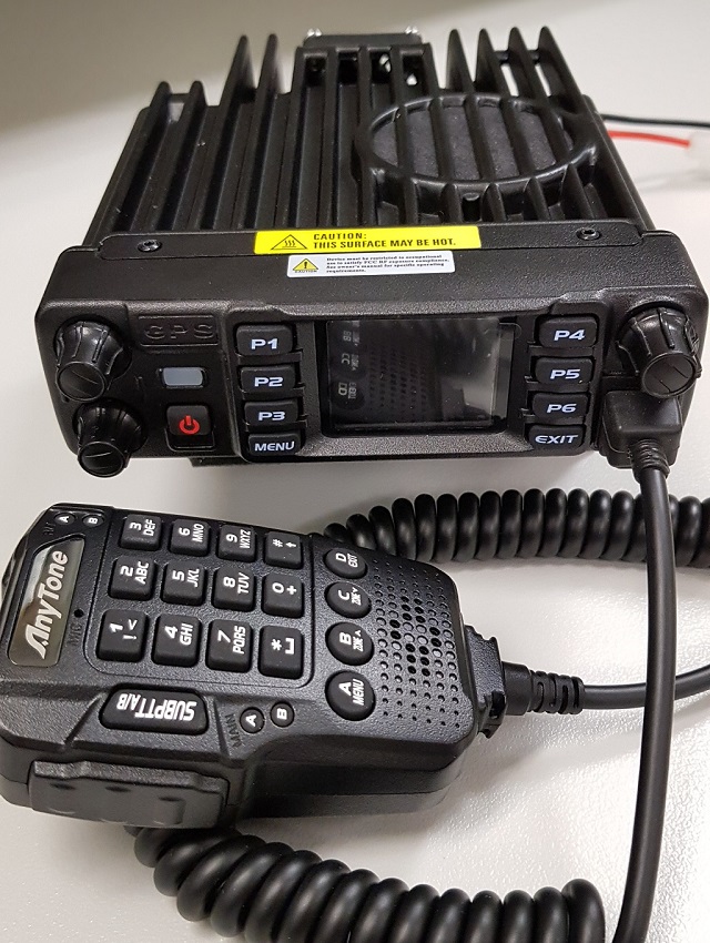
AnyTone’s AT-D578UV is a superb dual or tri band DMR & FM mobile radio. Anyone familiar with the AnyTone handheld 878 DMR handheld will instantly be at home using this radio. But the 578 is more than just an 878 crammed into a mobile radio case. Rated for 60 watt output on VHF and 45 watts on UHF, 4000 channels, 200,000 digital contacts, true simultaneous dual receive including dual same band RX, the 578 has been eagerly anticipated, and well worth the wait.
Presented here is a collection of modifications & technical information
for the 578. Not all of these modifications are my own ideas, and credit has
been given to the original author of the information as best as I have been
able to find. Each modification is rated on a difficulty scale as follows:
Easy: no specialist skills required, easy
soldering, minimal disassembly. If the thought of
picking up a screwdriver makes you break out in a cold sweat, however, you
might want to seek some assistance
Moderate: some skill required in soldering,
electronics and/or computing, some disassembly needed. Any self respecting ham
/ electronics geek will be comfortable at this level.
Advanced: excellent soldering skills required, very good knowledge of electronics and/or
computing, extensive disassembly.
If you have any more information or modifications that you’d like to share
here, please contact me at vk7zja at gmail dot com
and I will make sure you receive credit for your work, though you are welcome
to remain anonymous if you wish.
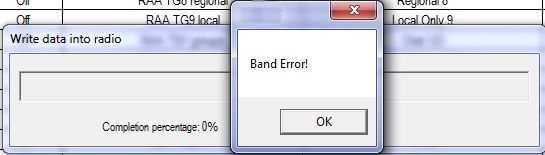
Arrgh, the dreaded ’Band Error’. This happens when the codeplug you try to write to the radio doesn’t match the operational band the radio is set to. The radio has certain band limits that can be changed to suit local requirements, and this can be set to one of several options by the user. If the codeplug that you are trying to write to the radio doesn’t match that setting, this is the error you will see.
There are four ways you can correct this issue. Choose the one that best suits you:
Method 1: changing the band of the radio to match the codeplug file you are trying to write (easiest method)
Download from this webpage here
Download via Mega
Download via Google Drive
Download via Sabercat host
Method 2: changing the band of the codeplug to match the radio (requires hex editing skills)
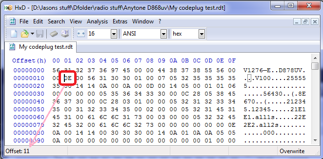
The red circle indicates byte 0x0011, which determines what band the codeplug is, change that data to 0E for band 14, or change it to 12 for band 18. Also note how the offset (address) shown in HxD indicates where your cursor is placed.
Method 3: when all else fails, use this export all / import all method (most reliable method, but needs the most work)
Method 4: change radio bands to match codeplug via radio Test Mode menus (if enabled)
What are the differences between the AnyTone AT-D578UV mobile and AT-D878UV handheld?
From a features viewpoint, the D578 has some extra functionality over and above the D878, such as:
Hint when using the programming software / CPS
When making changes or additions in the programming software, the changes or program additions you made don’t automatically ’take’ when you close the window. You must first select the ’OK’ button then close the window. This has caught me out several times, and though it might seem obvious when reading this, it is easy enough to overlook when slaving over your keyboard.
Virus detected! Is the CPS programming software really safe to use?
Some people have had a virus alert raised by their anti-virus software, declaring a quite specific virus when trying to download or install the CPS programming software. So is the software really safe to use? Yes, without doubt it is absolutely safe. There is no virus, this is a so-called ’false positive’ where the anti-virus software incorrectly thinks there is a virus present. This happens because the anti-virus software writers are basically lazy, their rationale is: we’ve never seen this executable before, therefore it must be unsafe. They do no intelligent analysis of the executable at all, and err on the side of paranoia. It’s obvious that this is the case as each different anti-virus software declares a different specific virus has been found, which can’t possibly be the case, if they were genuinely accurate findings.
So what can be done? Some anti-virus software can have exceptions made, while others can be temporarily disabled while you install the software. You will be safe, thousands of others have used the software, and to the very best of my knowledge no-one’s PC has yet been infected by the CPS software.
Hint when using the 578 microphone
Ever wondered why the up / down buttons on the top of the microphone don’t work? The answer is simple: the slide switch at the side of the microphone must be in the up position for these to work. It’s caught me out several times!
Hints & tips for upgrading firmware
Upgrading firmware on the AnyTone radio is easy, so long as you follow these general steps:
Yes, the thing will work with last firmware version’s codeplug, but strange things can & do happen. Laggy transmit, distorted alert tones, freezing, lockups and other miscellaneous issues have all been fixed by a fresh codeplug rebuild - a process made a lot easier with the export & import features of the software. This ensures the underlying data that your codeplug is built upon is fresh and consistent with the CPS and firmware version in use. Take the time to do this to ensure the best result.
If something goes wrong with the firmware update process, like a power failure in the middle of writing or the USB cable gets knocked, and corrupts the update to the point where the 578 won’t turn on or reset any more, follow this process that Sergey UA3ARF passed along:
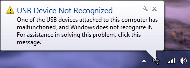
Trouble getting the drivers to install or work properly on Win 7 or 10
(Credit to Carsten Bauer VK6PCB, Chris Pyle & Duane Reese)
Some people have had problems with the drivers AnyTone / GigaDevice supplies to get the USB communicating with the radio when using Windows, especially Windows 10. Check these solutions to see if they can help you:
Strange error messages
Band Error has it’s own section, click here to see four different methods on how to fix this problem.
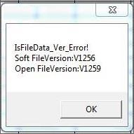
If you see something similar to this error message, it means you are trying to load a newer codeplug file than what your CPS software version can handle.
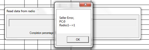
If you are getting this cryptic error message when trying to read or write to your radio, it means that your PC programming (CPS) software isn’t the same version firmware as what is on your radio. Always make sure you are using matched versions of CPS and firmware.
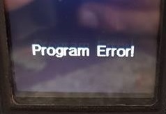
This error means your codeplug has become corrupt in memory. All you need do is perform a reset on the radio and reload the codeplug.

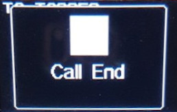
This error is a little more serious. A similar error message is ’Bad Block.’ Try the following, in order:

This error, or ’RTC ERROR!’ or ’RTC not run!’ means that, for what ever reason, the radio can not read the Real Time Clock. There is a pair of tiny internal batteries that backs up the Real Time Clock and keeps time when the radio is turned off. If either battery becomes too old, or goes faulty, you may see this error. If you continue to ignore this error message and the battery becomes so bad that it short circuits itself, then that could start to induce other new random errors such as the radio freezing up, not accepting any codeplug or firmware updates, and finally becoming completely unresponsive. A short circuit battery will drag down the microprocessor voltage supply, causing these random failures. The RTC backup battery can be replaced by getting access to the bottom side of the PCB and desoldering the old battery and replacing it with a new MS412 3 volt lithium battery - just make sure you get a MS412 already fitted with solder tabs. After fitting, a reset of the radio, setting the time & date and reprogramming the codeplug should set everything right.
Not really an error message as such, if you are seeing white blocks being displayed instead of an icon after you have made a firmware update, this means you need to also need to do an icon update to the radio. So far, the 578 has not had an icon update issued, but if you still find white squares appearing on the 578, you can use the latest 878 Icon file (it's the same as what is used in the 578): find Icon V1.20 update as part of the 878 V1.11 firmware update package. Once you have downloaded the package and located the Icon Update folder within, you send the icon .spi file to the radio by powering up the 578 in the icon update mode by holding down the DIAL and P1 buttons until UPDATE MODE is displayed. Then use the CPS menu selections Tool > Firmware and Icon Update and select the icon .spi file
Download the 878 icons package which uses the same icon file as the 578 (987kb) here:
Download via Mega
Download via Google Drive
Download via Sabercat host
A website with lots of great hints & tips for the AnyTone DMR radio family
(Thanks to Norman M6NBP and lots of others who contributed)
If you can’t find the answer you are looking for here, then this website is a real goldmine of information. It is the accumulation of many user’s experiences, hints and tips for all of the AnyTone DMR radio family. Take a look at: http://hamradio.joomla.com/anytone-dmr.html
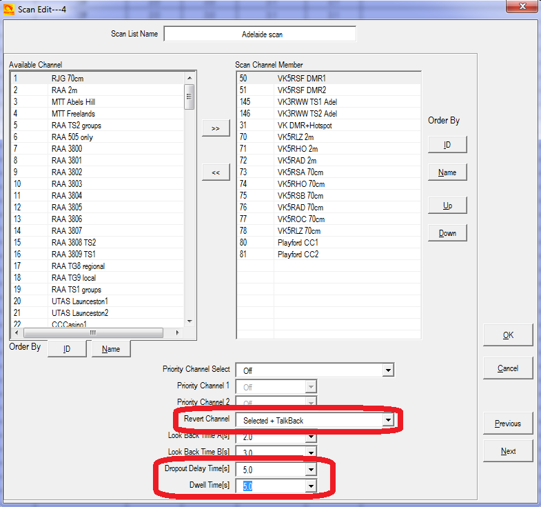
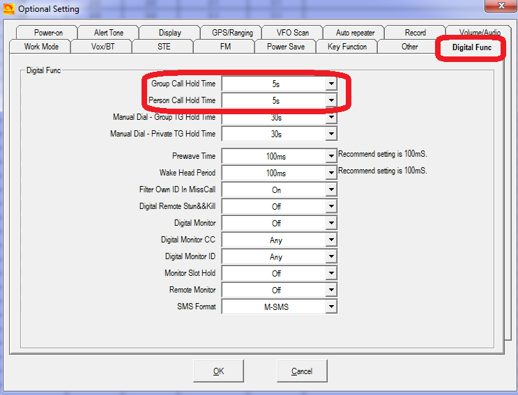
How to reply on an active channel found while scanning
When scan finds an active channel, it is possible to hit the PTT button to reply on that active channel found while scanning. Without these settings, the radio will transmit on your default channel, not the channel found during scan, which can cause some embarrassment. You will have to press the PTT within 5 seconds of the signal dropping, at which time scanning will resume again (5 seconds is the maximum scan hold time allowable).
For each and every scan list you have set up, change these settings as shown:
How do I reset the radio?
To reset the radio, turn it off, hold down the P2 button and dial knob, and press the power button, and keep holding those buttons while turning the radio on. Within two seconds you will see on the display ’Are you sure you want to Initialize radio?’. If you are sure you want to carry out the reset, press the MENU key and the radio will be reset, or press EXIT key to abort and not reset the radio.
Compatibility of encryption
Starting at firmware version 1.03, there are two voice encryption types available on the 578.
First is AES (Advanced Encryption Standard) which is definitely compatible with Motorola and Hytera products that also have AES enabled. To set this sort of encryption and have it successfully communicate to another AES encrypted radio you need to:
The other encryption type is called ’Common’. This encryption system is set up slightly differently:
You can only select one type of encryption in the 578 at a time: either AES or Common (Normal or Enhanced), not both at the same time. Also, encryption obviously only works on DMR digital channels.
Regarding compatibility, as already mentioned, AnyTone AES encryption is compatible with Motorola & Hytera AES encryption.
With the ’Common’ encryption - either in standard or enhanced mode - this is only compatible with other AnyTone 578 and 878s with the same settings. It is not compatible with other Chinese brand radios encryption, and it is not compatible with Motorola Basic Privacy or RC4 Enhanced Privacy.
The AnyTone radios will never be able to be compatible with Motorola Basic Privacy because that is a proprietary system that Motorola would not permit others to copy; and will never be compatible with RC4 Enhanced Privacy because the SCT3258 is physically unable to process DMR in the same way necessary to enable that particular encryption system.
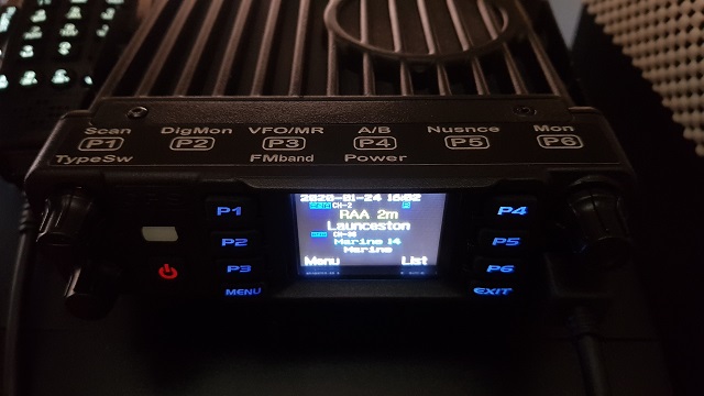
What about a remote head / display for the 578?
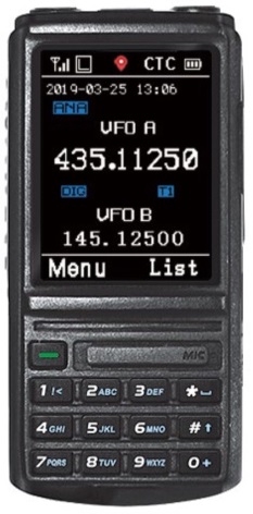
You may have noticed that there is no mention about a remote or removable head or display unit for the 578. AnyTone do have a solution under design now: rather than remote mounting the display, they are planning a Bluetooth remote microphone & control unit in one, complete with it’s own LCD display. There is no ETA on this microphone / control unit as yet, but if you keep an eye on the AnyTone related Facebook groups, it is likely to be announced there first. Here is an artist’s rendition of what the microphone might look like:
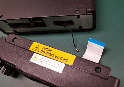
There might also be the possibility of a genuine remote head / display mount option. There is only the one flat ribbon cable connecting the display unit to the radio main body (the little coax cable connects to the GPS SMA connector; this could be replaced with a GPS antenna in the display unit as it has provision for it See: Add an internal GPS antenna to the 578), and if someone were able to source an equivalent 40 pin ribbon cable of a few feet in length and 3D print some backing plates to securely mount the display unit... who knows? It may be possible.
Bluetooth microphones and the 578
It has been found that some Bluetooth speaker microphones work perfectly with the 578. One of these is the Wandfu H2, which apparently works very well. AnyTone are developing their own Bluetooth microphone as well. If you find other brands of Bluetooth microphones that do work with the 578, let me know so they can be listed here for the benefit of all users.
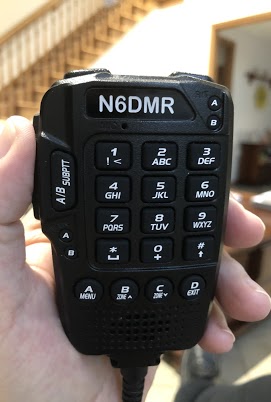
Custom engraved call sign labels for your radio
Thanks to Greg KC8GL, you can order a custom laser engraved self adhesive label for your radio that perfectly fits the AnyTone 578 microphone, at a very attractive price. Greg recommends using a black magic permanent ink marker pen to run a line of ink around the white edge of the labels to help hide the white substrate, touching off that professional look once the label is installed. Also check out the lovely cherry wood callsign display plaques that Greg does. I highly recommend them! Greg is a fantastic guy, quick to respond and happy to answer any questions you may have. See his website at: https://sites.google.com/view/kc8gl/d578uviii-pro-microphone-call-sign-sticker
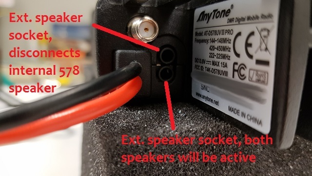
External speaker socket differences on the AT-D578UV
The below photo shows the difference between the two 3.5mm extension speaker sockets. The socket closest the GPS SMA antenna is for an external speaker which will disconnect the 578 internal speaker, while the other socket will keep the 578 internal speaker connected, and both speakers will be active.
Microphone socket pinouts & information AT-D578UV
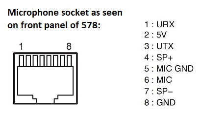
Here is a general schematic for building or adapting a base microphone to the AnyTone 578. You could use a surplus computer gooseneck microphone and modify that for this use.
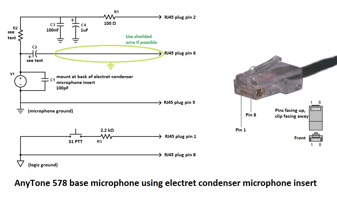
R2 can vary from 22k ohms down to 1k ohms, depending on the individual electret microphone insert used. Start with 22k ohms and reduce the value until you reach the microphone gain level desired. Too much gain will cause gross distortion and make your transmissions difficult and unpleasant to listen to.
R3 is 2.2k or 1.5k ohms.
C1 is 100pF and should be mounted directly on the back of the electret condenser microphone insert.
C2 can vary according to your personal preference. Use 10uF electrolytic for a stronger bass response, or 1uF electrolytic for normal use.
C3 is a 100nF (0.1uF) polyester or other similar bypass type capacitor.
C4 is a 1uF electrolytic capacitor.
V1 is an electret condenser microphone insert.
S1 is your PTT button.
Important: do not confuse microphone ground and logic ground in the diagram above. The two must be kept separate.
The above schematic could be adapted to using a dynamic microphone, but you will probably need to use a small amplifier in place of C2 to boost the very weak output of the dynamic microphone element. Power it using the same decoupling circuit shown using R1, C3 & C4. R2 is not necessary for dynamic microphone element operation.
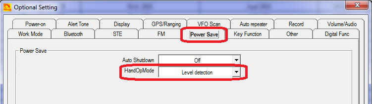
It is not possible to have both original AnyTone hand microphone and base microphone connected, or have some sort of switchable tee piece to be able to switch between the two. You can’t even manually swap between the two types of microphone unless you change the CPS setting first - if you leave the setting in Level Detection with the normal microphone connected, not only will the microphone or any of it’s buttons not work, but it will also randomly send the radio into transmit.
Modify the 578 microphone for external audio input and output for SignaLink etc. Moderate
With thanks to Tim N8NQH
For applications where you might want to connect external TX microphone audio and RX received audio to an external device, such as a SignaLink, TNC or RigBlaster etc. then this modification from Tim N8NQH is perfect. Read all about it at this link: http://tim-yvonne.com/ham/dmr/how-to/signalink-to-d578.htm
Using a Bluetooth module for external audio input and output for digital modes etc. Easy
With thanks to a ham who wished to remain anonymous
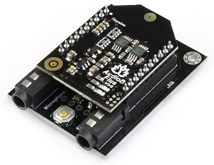
As an alternative to the above modification of the microphone for connection to a SignaLink, you can use some Bluetooth modules to get audio in and out of the 578, so you can then use digital modes etc. But apparently, many cheap USB Bluetooth adapters are not very good for this purpose. After much experimentation, one ham hit upon a nice little $12 Bluetooth module that works a treat. The TinySine Bluetooth adapter converts the Bluetooth connection to a standard pair of 3.5mm audio sockets, one for microphone in, the other for line out. Those are then connected to your PC with standard 3.5mm audio patch cables. It’s powered by a micro USB socket, but this doesn’t form the link to your PC, it is only used to power the TinySine. Easy!
There are a couple settings on the radio which you may want to change as well. Under the Bluetooth menu of the radio, there is a ’BT + int mic’ option: if turned on, you are able to use both the hand mic to talk, and the computer to send audio to the 578. There is also a ’BT + int spk’ option: you can decide if you would like to have audio come out of both the radio speaker, and out via Bluetooth going to the computer.
To send the radio into transmit, you must use AnyTone’s little Bluetooth PTT button. Another option is to set the HandOpMode to Level Detection (see above information on microphones ) and use whatever digital mode you are using control PTT, but you will then lose the ability to use the microphone as it must be unplugged for this option to work.
See more information about the TinySine here: https://www.tinyosshop.com/index.php?route=product/product&path=158_168&product_id=973
Hint when using a Bluetooth earpiece
From Martin G8FXC comes a hint about using a Bluetooth earpiece. He tested a Jabra Bluetooth earpiece which has a feature where the user can redial the last called number by double tapping on the ’answer’ button when used with a cell / mobile phone. When this was paired with the 878, it was found a double tap on the answer button would send the 878 into transmit, and a single tap would return to receive. Martin says he has tried a few different headsets and the only types he found that do this are the Jabra makes with a double tap to answer feature. It has also been found that the Plantronics M25 earpiece also works in this way. If you have a Bluetooth headset or earpiece with a similar feature, give it a try, it might work with your radio in the same way.
Custom background display files for your AT-D578UV
Tim DL2DMC has made available some very nice looking background display files for download from: http://www.geoo.de/AnytoneDL/D878UVscreens.zip
While these are intended for the 878, they will also work on the 578 too. If you have made your own background display image and would like to share it with others, please get in touch with me by email and I will place it here for everyone.

Chris 2E0UKH has made a video preview of these backgrounds and shows you how to upload them to the 878 - the process is practically identical for the 578 too. Take a peek at his YouTube video here: https://youtu.be/tPMhNEPVgjw
Using ’enhanced microphone audio’
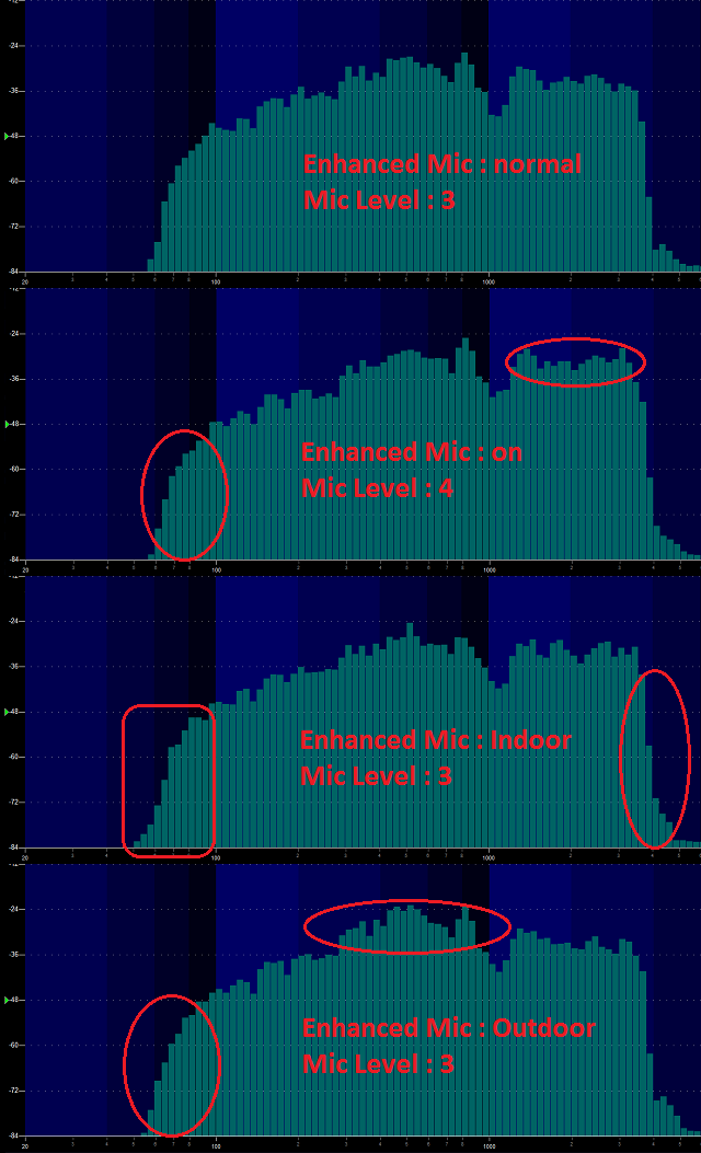
So just what does Mic Enhance (Settings > Radio Set > Enhance Sound > various options) do exactly? Firstly, lets talk about what it does not do. Enhance Sound does not have any effect on received audio at all, and it does not have any effect on transmitted analogue FM audio.
What these settings do is to subtly change your voice characteristics when transmitting on DMR.
Experiment with these settings to find the best setting for your situation. At the moment, the Indoor and Outdoor settings are only available from the radio menus, not within the CPS software.
Shown here is the transmitted audio response plots using a test audio clip transmitted using DMR:
Make your radio sound like a Motorola
You can set up your radio so the transmit permit tone sounds like that of a Motorola DMR radio.
Use these settings under Optional Setting > Alert Tone to give the distinctive MotoTRBO DMR chirp:
1st tone = 1570 Hz for 50ms (due to a current bug, this tone needs an extra 10ms more than necessary)
2nd tone = 1050 Hz for 40ms
3rd tone = 1570 Hz for 40ms
4th tone = 1320 Hz for 40ms
5th tone = 0 Hz for 0ms
Now when you press the PTT button the actual sound produced by the speaker is identical to the Motorola Transmit Permit Tone.
From Steve WA7PTM comes a fun tone sequence to try. You can use this for the Call Tone, Idle Channel Tone or Call Reset Tone, completely your choice.
1st tone = 1175 Hz for 200ms
2nd tone = 1319 Hz for 200ms
3rd tone = 1047 Hz for 200ms
4th tone = 523 Hz for 200ms
5th tone = 784 Hz for 200ms
Now you’ll hear the famous melody from Close Encounters of the Third Kind movie.
Or how about the melody Manah Manah made famous by The Muppets?
1st tone = 1397 Hz for 150ms
2nd tone = 1760 Hz for 150ms
3rd tone = 1976 Hz for 50ms
4th tone = 1568 Hz for 50ms
5th tone = 1318 Hz for 50ms
Using the address book to dial EchoLink nodes
Courtesy of Klaus DL5MCC
EchoLink is a system that allows amateur radio operators to communicate with one another via EchoLink ’nodes’ that are connected together by the internet. A regular analog FM radio is used to access each node. To connect to a certain node via a FM-Simplex Link (-L) or -Repeater (-R), you dial the node number just by transmitting the node number you wish to connect to using DTMF-tones. Described here is a method of using the analog address book to store, recall and dial node numbers at the touch of a button.
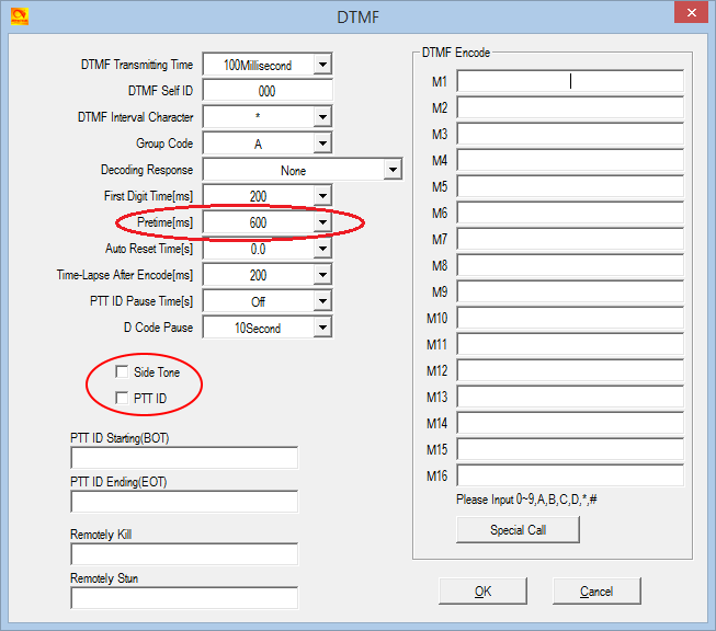
In use, to connect to an EchoLink node, select the frequency / channel of a nearby FM-Echo-Link Node (-L) or -Repeater (-L). Then press List (red button) and select the entry, you intend to call. With the desired entry highlighted, just press and hold PTT while the sequence of DTMF is transmitted.
Please note, that only DTMF-numbers can be stored in the analog address book. Any other characters (ABCD*#) required to control a link, must be entered manually by the keypad.
Known button held during power up sequences
There are several power up sequences which involve holding down buttons to invoke certain modes on the 578 as follows:
The test mode (P4 + dial) has three levels of access:
See the section below titled Enabling full test / self adjustment mode for more detail.
Selecting operational bands
There are many different choices of bands that you can select to use, which may change depending on firmware version.
Note that whenever you do change MODE, the radio will reset and you will lose your programmed data. Make sure you have a saved copy of your codeplug. Each saved codeplug will have the MODE it was created under encoded within it. If you try to reload the same codeplug after changing MODE, the CPS software will reject it, saying that it is the wrong band. To fix this, you will need to ’hex edit’ the codeplug rdt file: change byte 0x0011 to match the MODE selected. For example, if you set MODE=00002 then edit your codeplug byte 0x0011 to be hex value 02. Or if you set MODE=00010 then set codeplug byte 0x0011 to hex value 0A.
Begin by turning the radio off, then press and hold the P4 and dial buttons down while turning on the radio, hold those two buttons until you see ’TEST MODE’ appear on screen. After releasing the buttons the radio will start up with the text ’MODE:00000’ to the bottom of the screen
If you don’t see this screen, you will need to download AT Options software and enable ’Band select’ check box & write this back to the radio. See: Download AT Options software
Rotate the top dial to change the mode number, which will select the following:
Mode
578 v1.11 RX
578 v1.11 TX
0
400-480 & 136-174
400-480 & 136-174
1
400-480 & 136-174 (12.5k only)
400-480 & 136-174 (12.5k only)
2
430-440 & 136-174
430-440 & 136-174
3
400-480 & 136-174
430-440 & 144-146
4
440-480 & 136-174
440-480 & 136-174
5
440-480 & 144-146
440-480 & 144-146
6
446-447 & 136-174
446-447 & 136-174
7
400-480 & 136-174
420-450 & 144-148
8
400-470 & 136-174
400-470 & 136-174
9
430-432 & 144-146
430-432 & 144-146
10
400-480 & 136-174
430-450 & 144-148
11
400-520 & 136-174
400-520 & 136-174
12
400-490 & 136-174
400-490 & 136-174
13
400-480 & 136-174
403-470 & 136-174
14*
400-520 & 136-174 & 220-225
400-520 & 136-174 & 220-225
15
420-520 & 144-148
420-520 & 144-148
16
430-440 & 144-147
430-440 & 144-147
17
430-440 & 136-174
136-174 only
18
400-480 & 136-174 & 220-225
420-450 & 144-148 & 222-225
The bands that are indicated in grey above are not directly selectable via the test menu MODE selection. You can use AT Options application to select one of these hidden bands if you require.
I will not be sharing the password for MODE 00014 under any circumstances, as the FCC is starting to closely scrutinise these matters and we don’t them to revoke the approval status for these wonderful radios, which would result in the AnyTone radios being withdrawn from sale, then nobody would be able to enjoy them.
For the vast majority of users, there is no need to use MODE 00014 anyway. The alternate firmware files available at expanded RX frequencies with alternate firmware will permit out of band reception under any MODE selection, making MODE 00014 mostly redundant. If you have a genuine requirement for MODE 00014, then please see your dealer.
Expanding RX frequencies Easy
As delivered by the factory, the radio receiver covers 136-174 MHz, 400-480 MHz and 220-225 MHz. There are countries around the world that make use of the radio spectrum above 480 MHz for two way radio, and this modification will allow you to hear those transmissions. TX is intentionally inhibited in these expanded areas. The modification only opens up the radio hardware, some tricks are still necessary to program out of band frequencies with the software.
To carry out this modification do the following:
Download the frequency expanded / modified 578 firmware package (1.1 Mb) based on v1.11 firmware from:
Your mileage may vary of course, due to individual radio & component manufacturing tolerances. You can use the VFO and add memory channels to use these new expanded receive frequency ranges. Note that with the expanded frequencies, you can’t enter frequencies via keypad direct entry that start with a 3 or 5 (e.g. any frequency in the 300 or 500 MHz range) the only way to get to them is via lots of knob twisting in VFO mode.
Download via Mega
Download via Google Drive
Download via Sabercat host
To enter out of band frequencies in the CPS programming software, you will need to use the export-edit-import method: program some dummy channels with valid but easy to recognise frequencies, for example 456 MHz, then use the export feature (tool > export > channel > give it a name > export) and save your exported channels. Open the exported channels file with a text editor - look for your dummy channels you had previously entered, and edit the frequencies as you require, and save the file. Back in the CPS software, use the import feature (tool > import > channel > find your edited csv file > import) to bring the channels with out of band edited frequencies into the radio.
Transmit remains standard according to each MODE. Note that out of band receive frequencies can be very low in sensitivity due to the excellent front end filtering of these radios.
Refer to the sensitivity plots below:
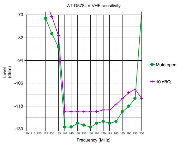
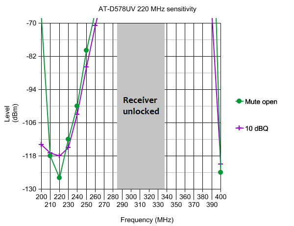
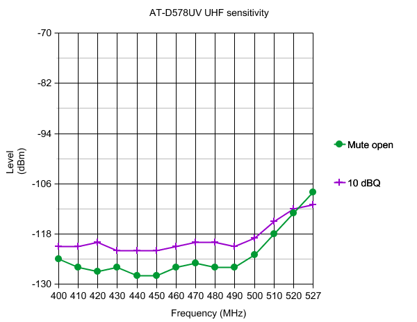
If you are wondering about the sensitivity measurements that are off scale of the above graphs, here are those results for 10dBQ:
110MHz= -34dBm; 115MHz= -22dBm; 120MHz= -49dBm
270MHz= -58dBm; 280MHz= -44dBm; 340MHz= -46dBm; 350MHz= -49dBm; 360MHz= -52dBm; 370MHz= -56dBm; 380MHz= -59dBm; 390MHz= -67dBm
While these power measurements were taken in analogue FM mode, they will be accurate for DMR as well. Note carefully that unless you have special power measuring test equipment, able to read peak pulse power with a duty cycle correction factor of 0.4615, then your simple power meter will not be able to correctly measure power output in DMR transmit, it will read much lower than the actual figure.
Test frequency
Low
Mid
High
Turbo
145.5 MHz
1.2
10
25
58
225.0 MHz
1.5
6.0
6.0
6.0
435.0 MHz
1.1
11
26
43
What about fortuitous air band (118-136 MHz) reception?
On the AnyTone 868 & 878, partial air band reception is possible when using modified firmware, with strong signals at least. Yes, the receiver is still FM and air band signals are AM, but by tuning just slightly off centre the AM signal can be resolved and heard, though with a little distortion.
So with the 578 able to quite happily tune down to 110 MHz with modified firmware, this should make it ideal for ’fortuitous’ air band reception, right? Unlike the 868 & 878, the mobile 578 appears to use a different RF transceiver chip, and unfortunately reception of AM signals in FM mode on the 578 is just too distorted to properly receive air band signals.
But all is not lost for those wanting to hear the air band on the 578. AnyTone have made provision on the PCB for extra components to be added to the 578 to give real AM reception. This will hopefully be coming in a future model of the 578 called the AT-D578UV PLUS model; it won’t be a plug in module that the user can add at a later date. This feature is currently under development by AnyTone, so keep an eye out for news from your dealer or the AnyTone Facebook groups.
My receive keeps cutting in and out on FM, can that be fixed?
Sometimes it has been reported that receive audio keeps cutting in and out, or popping, on FM signals. This is typically a problem for USA users listening to NOAA weather broadcasts. The cutting in and out happens slightly randomly, not at precise & regular intervals.
Other radios are not affected, so is the 578 at fault here? No, everything is fine - what is happening here is the signal you are listening to is deviating too widely for the 578 receiver to handle. Deviation peaks are being clipped by the 578 receiver, causing the audio to cut out briefly. There are a few things you can do:
The first thing to check is that you have the 578 receiver set to wideband FM (radio menus: Settings > Chan Set > Band width > Wide) which is the correct mode for listening to most ham activity in the USA and for NOAA signals.
Some users have reported that turning their STE settings to OFF helped
If the signal still cuts in and out, try disabling the squelch (radio menus: Settings > Radio Set > Ana Sq Level > Ana SQ OFF) - if the signal is now OK, it is almost certain that the signal you are listening to is too widely deviated for the 578 receiver to handle. Some NOAA signals are still transmitting with the very old 30 kHz standard deviation, which is too wide for the standard 25 kHz and much too wide for 12.5 kHz.
There are other conditions where the radio receiver may cut in and out too: very complex multipath environment or strong off-frequency or out of band signals can also upset the receiver and mimic this effect. In those instances, a change of antenna or location may help.
Expanding FM band frequencies 76 to 120 MHz Easy
The present firmware version only permits FM band VFO tuning from 87.5 to 108 MHz. The software however, permits entry of frequencies from 76.0 to 108.0 MHz for memories in the FM band. This is the easiest way to get the 578 to tune down to 76 MHz - put those frequencies into a FM band memory channel. Tuning below 76 MHz isn’t possible at this stage as the RDA 5802 needs to be set up differently to go below 76 MHz. But going up past 108 MHz is possible, - though I’m not sure why you’d want to. Reception of air band transmissions using wideband FM, even with a very strong AM signal, is impossible. But, if you have the need to, I found that my 578 was able to receive test signals all the way up to 120 MHz. Entering such frequencies is quite easy, all you need to do is to enter some ’dummy’ channels, and then using the Tool > Export menu in the CPS programming software, export your FM channels and open the file with Notepad for editing. Change the frequencies of the dummy channels you entered and save the file, then use the Tool > Import menu in the CPS programming software to import your edited file. This way you can enter any FM frequency, in 50 kHz steps, between 76.00 and 120.00 MHz. You can edit and import frequencies outside these limits, but the receiver won’t actually work properly beyond those limits.
Changing the display font / modifying some of the icons Advanced
(Credit to Colin G4EML & Ronan EI4KN - the ’font master’ hihi)
Would you like to change the display font on your 578, and don’t mind getting your hands dirty with a hex editor and a few other tools?
There are six different fonts encoded into the 578 firmware .CDD file. The location within the firmware file at which the fonts are encoded will change from version to version. Therefore, the first thing you need to do is identify exactly where the fonts you want to replace are located. To make this job easier, Colin G4EML has created a small executable which allows you to graphically view a file as a bitmapped image.
Download Colin G4EML ImageTest (15kb) software from:
Download from this webpage here
Download via Mega
Download via Google Drive
Download via Sabercat host
Be aware that the bitmapped icons and fonts are vertical raster, not horizontal. It could take a lot of scrolling through the file to identify the font, but the auto step feature makes life a lot easier.
In the 578 firmware, there are six font sizes: 7x10 H x W starting at 0x08CEDF; 8x8 H x W starting at 0x08CF7C; 12x12 H x W starting at 0x08D16E; 16x16 H x W starting at 0x08DA5E; 24x11 H x W starting at 0x08E641; and a super large 24x16 font starting at 0x08F376. Other symbols such as the antenna signal meter etc. will be found starting at 0x08FBC8. These addresses / locations are only valid for firmware version 1.05, the exact locations will change a little in other versions.
Once you find the location of the font you want to play with, make a note of its starting location. Now you’ll want to create a font of the same size. A very useful tool to convert fonts from your computer into bitmaps is Rays Font Editor which you can download here:
http://www.rayslogic.com/Software/RaysFontEditor/RaysFontEditor_24Aug12.zip (3.0 Mb)
Make sure you convert the font to the same size as the one you are going to replace. To use Rays Font Editor to produce a bitmap ready for the 578:
- Install your desired TTF font as a system font on your PC
- Select Capture System Font, then select your desired font from the list
- Select input size by point, and play around with the value to get each character fully visible. Typically the letters M and W are difficult to fit width wise and get truncated at the sides, and lower case letters g, j, p, q and y can get cut off at the bottom: try smaller point values to get the font small enough to fit or manually tweak the problem letters yourself. As an example, the Courier New TTF font works well if imported at 10 point size
- Select Output character size - Change font size and enter height and width to suit the font you are replacing, and click OK
- Examine your characters that have been imported to make sure they all fit nicely and are fully legible. You can edit the appearance and shift characters up/down/left/right to make them look nice.
- Select Font settings, and choose character range starting at 32 and ending at 126, as those are the only characters the 578 needs
- Select Export font. You want to select ’custom’, format is binary file, scan direction set to start top-left, scan vertical and leave the other settings as they are. Give your font a name and save it
- Rename the extension of your font from a .dat to .bin and you have a file that’s ready to go into the 578.
Now it is simply a case of using your hex editor to copy this binary data from the file you just created over the top of the font data in the firmware file, at the start address you noted earlier. If using HxD, use paste write, not paste insert when copying your new font binary data into the firmware image. Write the firmware to your 578 and enjoy a new look display.
Multi-coloured icons, other than the basic mono-chromatic symbols, are mostly stored in the 578 flash memory locations 0x0015A000 to 0x00200000. The 578 currently uses the same icons as the latest 878, and so you can use the 878 Icon V1.20 update as part of the 878 V1.11 firmware update package to write to those memory locations. As a result, if you want to play with custom icons, it is easiest to edit a copy of the 878 icon file called D878_1G_ICON_V1.20_20190226.CDD if you want to customise some of your coloured icons. They are encoded as RGB565 raw bitmap format, and of varying sizes. You could use a raw bitmap viewer to explore the contents of the icon update file. A good website to do this is located at: http://rawpixels.net/
For full screen bitmaps such as the start up image, select a width of 128 pixels, height of 160 pixels, select Flip V, select Predefined format of RGB565, and make sure Little Endian is not selected. For other icons you will need to play around with the width and height, but should use the same settings.
A few other coloured icons are encoded into the firmware image, the main one there being the 11x11 digital monitor speaker symbol.
Enabling full test / self adjustment mode Advanced
(Credit to Colin G4EML and Jason VK7ZJA)
Warning: you can seriously mess up your radio with this adjustment mode to the point that it may not transmit, receive, or even have a visible display with careless changes to certain values. If you do not know what you are doing, leave this alone.
There is a way to enable the full test mode menu on the radio so you can not only alter the operational bands, but also things like setting Turbo, High, Mid & Low RF output power levels individually, fine tune the frequency, set the tight squelch values, change the received signal strength S-meter (RSSI) meter curve, even calibrate the battery voltage readout.
Begin by connecting your radio to the CPS software and take a screenshot of, or write down the information shown in the ’Local Information’ screen. This is very handy information to keep. Also ensure you have saved a copy of your current codeplug
Colin G4EML has created an application called AT Options, which will allow you to enable the full test mode, enable a programming password (more about this below) and to edit other text such as the dealer you purchased your radio from, or any maintenance notes you might like to add. For example, you can enter your name, phone number and callsign in this text area in case your radio is stolen.
Download Colin G4EML AT Options version 6 (17kb) software from:
Download from this webpage here
Download via Mega
Download via Google Drive
Download via Sabercat host
*As always, this software is provided without any warranties, and you use it entirely at your own risk. Using this application to write any changes to your radio is also likely invalidate the manufacturer’s warranty
(The application is also suitable for the AnyTone 878 & 868, Btech 6X2 and Alinco DJ-MD5)
Ensure that you do not have any power on password active. If you do, you must use the CPS software to remove it first. Use of AT Options while a power on password is active can, under certain circumstances, cause some data to be overwritten with default data.
When you run the software, select your COM port and READ from the radio. Then edit any text fields you may want, and make sure Band Select and Full Test Mode check boxes are ticked. Finally, WRITE the settings back to the radio - this only takes a fraction of a second to do, and the radio will reboot. It may take a few extra seconds more than normal to boot up, this is OK as it is reconfiguring internal memory.
To activate test mode, turn off the radio, hold down the P4 and dial buttons while turning on the radio until TEST MODE is displayed on the radio screen (this takes a few seconds to happen), then let the two buttons go. The radio will boot up into it’s full test / self adjustment mode.
Once you start test mode, scroll up and down between different test adjustment points using the zone up/down button. The following adjustments are available:
I strongly recommend you go through each setting and write down what they are before making any adjustments
| 578 Setting | Adj. range | Description | Typical value | |
|---|---|---|---|---|
| 1 | UHF AL | nil | A-VFO Low UHF test frequency | |
| 2 | UHF AM | nil | A-VFO Mid UHF test frequency | |
| 3 | UHF AH | nil | A-VFO High UHF test frequency | |
| 4 | VHF AL | nil | A-VFO Low VHF test frequency | |
| 5 | VHF AM | nil | A-VFO Mid VHF test frequency | |
| 6 | VHF AH | nil | A-VFO High VHF test frequency | |
| 7 | UHF BL | nil | B-VFO Low UHF test frequency | |
| 8 | UHF BM | nil | B-VFO Mid UHF test frequency | |
| 9 | UHF BH | nil | B-VFO High UHF test frequency | |
| 10 | VHF BL | nil | B-VFO Low VHF test frequency | |
| 11 | VHF BM | nil | B-VFO Mid VHF test frequency | |
| 12 | VHF BH | nil | B-VFO High VHF test frequency | |
| 13 | FQCA | 0-255 | A-VFO Frequency fine tune | 41 * |
| 14 | TXDAU | 0-255 | Unknown UHF analogue adjustment | 150 |
| 15 | PAHU | 0-255 | UHF RF power output turbo setting | 207 |
| 16 | PAMU | 0-255 | UHF RF power output high setting | 182 |
| 17 | PALU | 0-255 | UHF RF power output medium setting | 154 |
| 18 | PASU | 0-255 | UHF RF power output low setting | 112 |
| 19 | MODU | 0-255 | Overall deviation setting for UHF | 105 |
| 20 | MIC | 0-63 | Microphone gain set | 54 |
| 21 | TONEU | 0-255 | Transmit audio tone level, push PTT to transmit a test 1000 Hz tone on displayed UHF FM frequency | 98 |
| 22 | TONEV2 | 0-255 | Transmit audio tone level, push PTT to transmit a test 1000 Hz tone on displayed VHF FM frequency | 40 |
| 23 | CTCW | 0-128 | Deviation setting for CTCSS in both UHF & VHF | 39 |
| 24 | DCSW | 0-128 | Deviation setting for DCS in both UHF & VHF | 28 |
| 25 | BPFLUA | 0-255 | UHF A-VFO receive tracking gain, low end of band | 35 |
| 26 | BPFMUA | 0-255 | UHF A-VFO receive tracking gain, mid band | 135 |
| 27 | BPFHUA | 0-255 | UHF A-VFO receive tracking gain, top end of band | 253 |
| 28 | BPFLUB | 0-255 | UHF B-VFO receive tracking gain, low end of band | 35 |
| 29 | BPFMUB | 0-255 | UHF B-VFO receive tracking gain, mid band | 145 |
| 30 | BPFHUB | 0-255 | UHF B-VFO receive tracking gain, top end of band | 253 |
| 31 | AGCUA | 0-255 | UHF A-VFO AGC (suspect receiver gain related) | 180 |
| 32 | AGCUB | 0-255 | UHF B-VFO AGC (suspect receiver gain related) | 170 |
| 33 | SQTHUA | 0-255 | UHF A-VFO squelch tight threshold | 90 |
| 34 | SQTHUB | 0-255 | UHF B-VFO squelch tight threshold | 100 |
| 35 | RSSIUA | nil, only displays current value | UHF RSSI A-VFO, inject RF at desired level for 1 bar reading, rotate dial to sample and lock in value | 72 |
| 36 | RSSIUB | nil, only displays current value | UHF RSSI B-VFO, inject RF at desired level for 1 bar reading, rotate dial to sample and lock in value | 75 |
| 37 | A OBH | 0-65535 | unknown A+D adjustment | 3000 * |
| 38 | A OBL | 0-65535 | unknown A+D adjustment | 2700 * |
| 39 | D OBH | 0-65535 | unknown D+A adjustment | 3000 * |
| 40 | D OBL | 0-65535 | unknown D+A adjustment | 2700 * |
| 41 | D FSKLU | nil | Push PTT to send test FSK signal (heard as 2400 Hz on FM receiver) at low end of UHF band | |
| 42 | D FSKMU | nil | Push PTT to send test FSK signal (heard as 2400 Hz on FM receiver) at mid UHF band | |
| 43 | D FSKHU | nil | Push PTT to send test FSK signal (heard as 2400 Hz on FM receiver) at high end of UHF band | |
| 44 | D 600HzU | nil | Push PTT to send test 600Hz signal UHF band (heard on FM as 200 & 400 Hz?) | |
| 45 | D 300HzU | nil | Push PTT to send test 300Hz signal UHF band (heard on FM as 800 Hz?) | |
| 46 | D 1031U | nil | Push PTT to send 1031 test sequence UHF band, heard on DMR as 1031 Hz | |
| 47 | D BERU | nil | Display received BER of received UHF DMR signal | |
| 48 | D DIGI | nil | Test UHF DMR for both TX & RX as if it were on a regular DMR channel | |
| 49 | TXDAV | 0-255 | Unknown VHF analogue adjustment | 145 |
| 50 | PAHV | 0-255 | VHF RF power output turbo setting | 177 |
| 51 | PAMV | 0-255 | VHF RF power output high setting | 124 |
| 52 | PALV | 0-255 | VHF RF power output medium setting | 88 |
| 53 | PASV | 0-255 | VHF RF power output low setting | 40 |
| 54 | MODV | 0-255 | Overall deviation setting for VHF | 50 |
| 55 | MODV2 | 0-255 | Overall deviation setting for 222 MHz | 105 |
| 56 | BPFLVA | 0-255 | VHF A-VFO receive tracking gain, low end of band | 3 |
| 57 | BPFMVA | 0-255 | VHF A-VFO receive tracking gain, mid band | 135 |
| 58 | BPFHVA | 0-255 | VHF A-VFO receive tracking gain, top end of band | 253 |
| 59 | BPFLVB | 0-255 | VHF B-VFO receive tracking gain, low end of band | 0 |
| 60 | BPFMVB | 0-255 | VHF B-VFO receive tracking gain, mid band | 135 |
| 61 | BPFHVB | 0-255 | VHF B-VFO receive tracking gain, top end of band | 253 |
| 62 | AGCVA | 0-255 | VHF A-VFO AGC (suspect receiver gain related) | 170 |
| 63 | AGCVB | 0-255 | VHF B-VFO AGC (suspect receiver gain related) | 170 |
| 64 | SQTHVA | 0-255 | VHF A-VFO squelch tight threshold | 70 |
| 65 | SQTHVB | 0-255 | VHF B-VFO squelch tight threshold | 80 |
| 66 | RSSIVA | nil | VHF RSSI A-VFO, inject RF at desired level for 1 bar reading, rotate dial to sample and lock in value | 61 |
| 67 | RSSIVB | nil | VHF RSSI B-VFO, inject RF at desired level for 1 bar reading, rotate dial to sample and lock in value | 68 |
| 68 | D FSKLV | nil | Push PTT to send test FSK signal (heard as 2400 Hz on FM receiver) at low end of VHF band | |
| 53 | D FSKMV | nil | Push PTT to send test FSK signal (heard as 2400 Hz on FM receiver) at mid VHF band | |
| 70 | D FSKHV | nil | Push PTT to send test FSK signal (heard as 2400 Hz on FM receiver) at high end of VHF band | |
| 71 | D 600HzV | nil | Push PTT to send test 600Hz signal VHF band (heard on FM as 200 & 400 Hz?) | |
| 72 | D 300HzV | nil | Push PTT to send test 300Hz signal VHF band (heard on FM as 800 Hz?) | |
| 73 | D 1031V | nil | Push PTT to send 1031 test sequence on VHF band, heard on DMR as 1031 Hz | |
| 74 | D BERV | nil | Display received BER of received VHF DMR signal | |
| 75 | VBAT | undetermined | Calibrate displayed voltage. Do not adjust, otherwise radio will warn of incorrect voltage and prevent any further adjustments | 109 * |
| 76 | F1 A0 | 0-65535 | Hex BCD combination of mic gain and mic AGC values, however adjusting has no effect | 42512 |
| 77 | MODE | 0-18 | Changes operational frequency bands of radio | |
| 78 | 087.50M | nil | Receiver test of FM broadcast band | |
| 79 | 097.50M | nil | Receiver test of FM broadcast band | |
| 80 | 108.00M | nil | Receiver test of FM broadcast band |
For the squelch threshold values, a higher value gives a more sensitive squelch, but no improvement to sensitivity is obtained with values higher than about 112 to 114. Lower values require progressively stronger signals to open the squelch.
The RSSI (received signal strength indicator - in other words the signal meter) has a fairly compressed range of 15dB. I’d have preferred to see at least 30dB range in the signal meter, but I’ve found an acceptable compromise has been to set one bar at -113dBm which equates to values of RSSIU of 36 and RSSIV of 39. The signal meter then reads:
- 1 bar -113 dBm or about S-5
- 2 bars -108 dBm or about S-6
- 3 bars -103 dBm or about S-7
- 4 bars -98 dBm or about S-9
You can download a more comprehensive memory map of how each individual adjustment setting is stored in memory, and see more hidden values that are obviously used for RF alignment purposes, but are not available in this test mode. To experiment and adjust those you will need to use Flash Utility to create your own custom binary image, and write your own custom CDI and SPI files to enable that data to be written to the radio (Flash Utility can’t write to that area of memory directly, it is safest to write using the Icon update mode with a CDD, CDI & SPI file set).
Download the more comprehensive memory map (11 kb) from here:
Download from this webpage here
Download via Mega
Download via Google Drive
Download via Sabercat host
If you've forgotten your power on password where the radio displays PLEASE INPUT THE PASSWORD! and will not let you go any further until you do, this will help you recover it and remove the password. Resetting the radio will not bypass this password check.
- Do not connect your programming cable yet. Power up the radio and wait until it asks for the password
- Only now should you connect your programming cable, and using the CPS software, read the radio
- Go to the menu: Optional Setting > Power-on > Power-on Password Char and you will see your password. Record your password somewhere safe
- Remove your programming cable, as you won’t be able to write back to the radio at this stage
- Power cycle the radio and log in with the password you read in step 3 above
- Using the radios own menus only, turn off the password check: Menu > Settings > Radio Set > Start Up Pwd > Off.
- Power cycle the radio again and confirm you are not asked for a password this time
- Now reconnect your programming cable, use the CPS software to read from the radio, and remove the power on password entirely
If your password has become corrupted in memory and the password read is anything other than pure digits, then your only option is to do a full defrost of the radio. A quick defrost will not work.
Apart from the power on password, there is also a hidden programming password that will require a four character password to be entered in the CPS software before it will do any read or write operation. The password must be four characters, no more or less, and can be made up of any standard ASCII characters that can be typed on a keyboard. To do this, use Colin’s AT Options application (download link in the Enabling Full Test / self adjustment mode section above) to enter a Program Password. To disable any program password that may be present, just use the backspace button to delete the password and leave this field blank; then write back to the radio.
FCC Part 90 approval information:
The FCC has documented quite a bit of interesting technical information regarding the 578 regarding their Part 90 approvals. You can find internal photographs, test reports, SAR radiation exposure limit testing reports and more. Visit the FCC report pages at:
https://fccid.io/T4K-D578UV
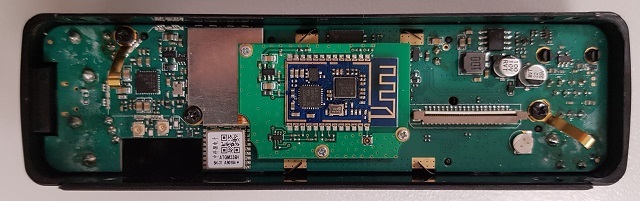
A look inside the 578
The back side of the display board. The GPS module ATGM336H is capable of tracking GPS & BDS (BeiDou) positioning systems. Also visible is the Bluetooth module.
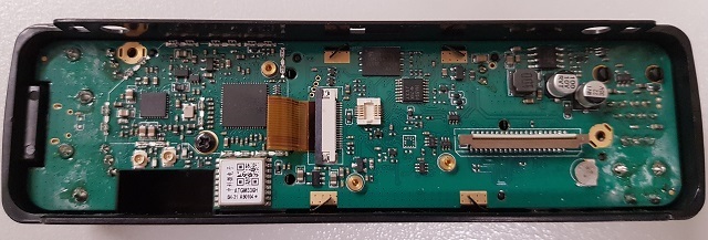
The back side of the display board. Bluetooth removed.
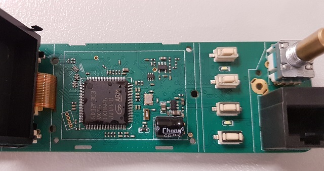
The front side of the display board.
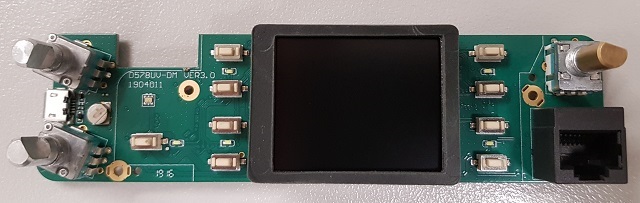
578 MCU hides under the LCD display:
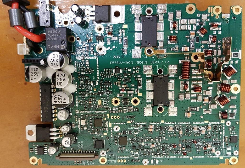
The 578 main board top side:
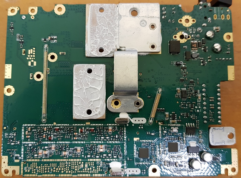
The 578 main board under side:
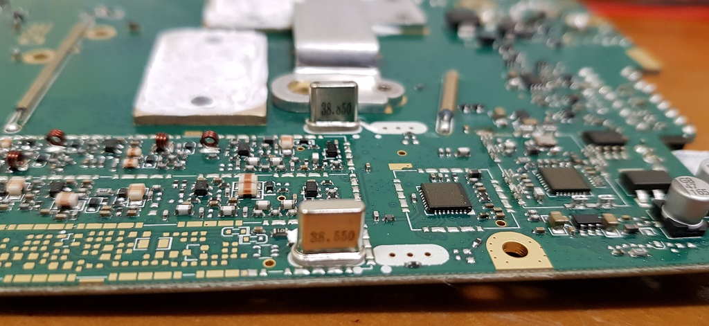
Close up of the twin 38 MHz IF crystal filters. Note the unpopulated PCB lands for a future version of the 578 that will have air band RX.
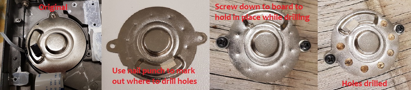
Modifying the internal speaker for extra volume Advanced (extensive disassembly)
The internal speaker of the 578 can be made to be slightly louder. Testing shows a 2dB improvement in output volume, which isn’t a lot, but might make the difference if you’re in a noisy environment.
The theory behind this modification is that with a solid backing plate behind the internal speaker cone, this increases the back-pressure on the cone as it vibrates back and forth producing sound. If holes were to be drilled in this backing plate, air will be able to be more freely move out of the way of the speaker cone, restricting it less and allowing it to move more freely, generating a higher output volume.
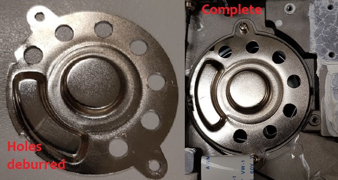
Begin by disassembling the radio - quite a lot of disassembly is necessary to get to the back of the speaker, including unsoldering the antenna connection. Once you have free access to the speaker backing plate, remove it, mark out a series of holes evenly around the perimeter and mark them with a nail punch. To make the job of drilling out 5mm holes easier, screw the plate to a piece of scrap timber. Once the holes have been drilled, de-burr them and reinstall the backing plate. Ensure the foam pad that was originally between the back of the speaker and the backing plate is put back into place, and screw the backing plate down firmly, and finally reassemble the radio.
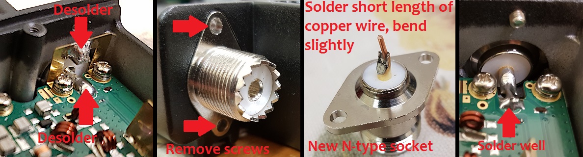
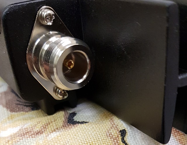
Replacing the SO-239 socket with an N-type socket Moderate
I get why a SO-239 socket has been fitted to the 578. Many hams use them, mainly because that is what a lot of other radios use too. There is a lot to be said for maintaining the status quo. But the SO-239 is a 90 year old design, they don’t maintain a constant 50 ohm impedance, and are usually only good to use up to 100 MHz. It’s about time that we ditch the SO-239 / PL-259 combination and upgrade to something a bit better. The N-type connector is a much better choice: good to at least 1 GHz and high quality types are usable up to 18 GHz, they also maintain a constant 50 ohm impedance across the connection, and not that it matters in this application, they also have a degree of weatherproofing over and above the SO-239 / PL-259 series.
Key benefits:
- Higher quality, better design connector, less ’junk’ connectors around in the N-type
- Slightly lower loss, especially at UHF
- Better VSWR / return loss; SO-239 connectors have an impedance ’bump’
- Better weatherproofing than SO-239 / PL-259 types
To replace the SO-239 socket with an N-type on the 578, first desolder the centre and earth pins of the socket as shown below. Then undo the screws holding in the socket, and it should fall right out. Also remove the brass square U shape ground bracket, but replace the screws that held it in. Test fit your replacement N-type socket to make sure it fits nicely. If all is good, solder a short bit of 1mm thick solid copper wire to the N-type socket centre pin, and bend it slightly upwards. Fit the new socket in the radio chassis and refit the screws that hold the socket flange. Make sure the screws are done up quite snugly, but not so over-tight that you strip the threads. Lastly solder the centre pin on to the PCB, clean up any flux that might be left behind and the job is done.
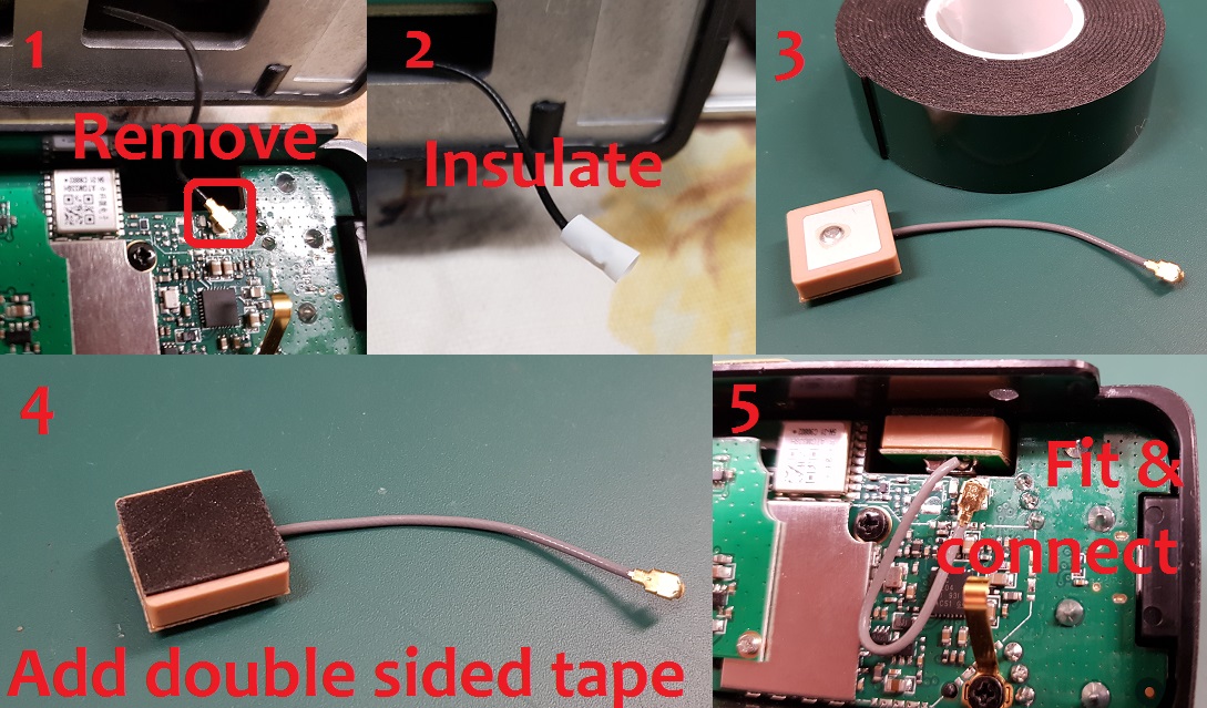
Adding an internal GPS antenna to the 578 Moderate
If you have a GPS equipped 578, you will have received an external GPS ’mouse’ style antenna that connects to the rear panel SMA socket. This is all very good, but what happens if you don’t want to use an external GPS antenna? The 578 was originally designed to have an internal GPS antenna too, but in the end the factory decided to rely solely on an external GPS antenna. It isn’t hard to understand why, either. With many 578s destined to be installed in vehicles, an external GPS antenna offers the very best performance in picking up the incredibly weak signals from orbiting GPS satellites as you drive under trees, into deep valleys or just in and around the city with lots of obstructing buildings.
However, if you are happy to sacrifice the performance of an external GPS antenna, you could add in your own GPS antenna to the display unit of the 578 and make use of that instead. There is space within the display unit, just behind the "GPS" inscription above the front panel LED in fact, where you could install your own mini GPS antenna. This space measures 19mm wide by 7mm high, and has an available depth of 20mm maximum. You will need an ’active’ (built in amplifier) type of antenna that is this size or smaller, and works for 1575.42 MHz - this is suitable for GPS and BeiDou GNSS, which the ATGM336H receiver works with. The 15x15mm types, which came with a short tail of mini coax and ending in a u.FL / IPX connector, cost a fraction over USD $3 each from eBay. Search for ’GPS active IPX antenna’ and look for the 15x15mm model (or 18x18mm types but those are a bit more expensive). It may be worthwhile buying a pack of four of these antennae for USD $8, and then you can cherry pick the most sensitive antenna. I found one of the four antennae I purchased was consistently taking about twice as long as the other three to get a position fix. Installation is simplicity itself:
Begin by removing the four Torx T8 size screws of the underside cover of the 578, and remove the two top side Torx T8 screws on the back lip of the display unit and carefully separate the display unit from the main body of the radio. Don’t pull it out too far or you will damage the connecting ribbon cable. Then:
- Unclip the existing u.FL connector that goes to the rear mounted SMA socket
- Insulate the original u.FL connector and tuck it away somewhere; a little bit of 2mm or 3mm heatshrink is a professional way to do this, but some electrical tape is OK too
- Find some double sided tape (maximum of 1mm thick). The double sided foam tape pictured here is used in the automotive industry to affix exterior trim to vehicle bodies etc. and works well
- Add a small square of double sided tape to the top of the GPS antenna
- Clip in the new antenna connector - due to it’s tiny size, this can be a bit tricky to get mated correctly, be patient and don’t force it. Mount the new antenna in the cut out as shown below
In some 578s, you may find there are two u.FL / IPX GPS antenna connectors. If this applies to you, test your GPS antenna in both sockets; I found that connecting the new internal GPS antenna to the socket closest the volume control resulted in a consistently faster lock. You can also still keep the existing fly lead for the external SMA GPS socket connected to the other u.FL / IPX socket, and even have both GPS antennae connected and working at the same time, it doesn’t seem to upset the performance getting a position fix.
Improved cooling for the 578 Moderate
The 578 isn’t meant for high duty cycle transmit, such as that which many ham operators tend to do. Generating 60 watts of output in such a compact body means the radio will heat up quickly, there is no getting around that. This alone is a very good reason to operate using the lowest power possible for your requirements. However, if you simply must use high power for anything other than a very brief call, then there are things that you can do to improve the cooling of the 578 in these circumstances.
The first change to make is to reverse the direction of the airflow over the heatsink fins of the radio body, which is done simply by turning the fan around. Undo the four screws holding the fan to the back of the 578 chassis, and turn it around so it faces the other way. The fan will now blow air over the heatsink, rather than drawing or sucking air past the heatsink fins. This seems to be more efficient at cooling the radio. If you are handy with a bit of sheet metal or a 3D printer, you can also make a small cowl to place over the back of the heatsink fins, which will help direct airflow over them, further improving cooling efficiency. The difference isn’t huge, but worthwhile.
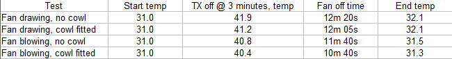
However, if you are often going to be using high power, it would be a much better idea to fashion a bracket to hold a 120mm computer fan to the top of the heatsink. Noctua make some excellent quality, very acoustically quiet fans that would be excellent for this job.
Improved receiver shielding for the 578 Advanced
While the radio case is metal and provides a good degree of shielding for the 578 receiver, AnyTone provided the PCB lands to add extra shields over the receiver section. You can manufacture your own shields out of 0.8mm tin plate or brass plate and solder them over the receiver PCB. Make each shield just slightly smaller than required, so the sides fit just on the inside edge of the PCB lands provided. Each shield should be at least 2.5mm high to allow a reasonable clearance from the receiver components underneath. Use a 60+ watt soldering iron to run a fillet of solder around the shields. You might not be able to solder all PCB lands due to the close proximity of other components, that is OK, just leave those alone rather than risk burning a nearby component. The end result should look like this (added shields indicated by red arrows:)
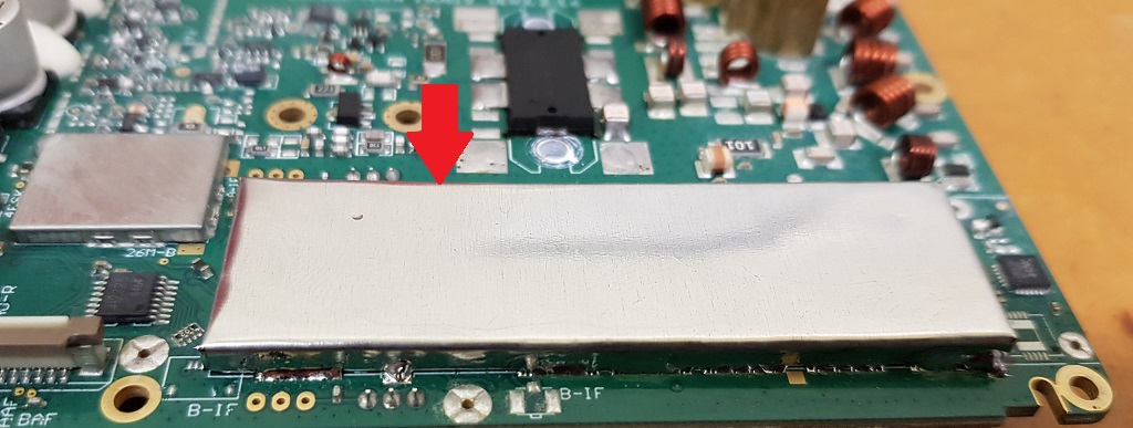
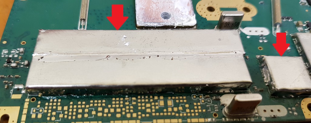
If done properly, this will result in a 2dB noise reduction on VHF, raising sensitivity by the same amount. No improvement on UHF was noticed.
General technical information
The 578 uses a hybrid receiver, with a conventional super-heterodyne 1st IF stage using 38.550 and 38.850 MHz Intermediate Frequencies, each followed by a direct conversion IF receiver. There is a relay and substantial diode for reverse polarity protection, and a third IF strip that is unpopulated; in future models of the 578 this will be the AM air band receiver.
The following devices are found within:
- GD32F303VKT6 ARM Cortex-M4 32 bit MCU with 3072kbyte internal flash and 96kbyte internal SRAM
- Toshiba TC58CVG1S3HRAIG 2Gbit / 256Mbyte NAND flash memory
- Sicomm CT3258TD baseband processor for DMR with built in AMBE2+ vocoder & 12.2 MHz oscillator
- Texas Instruments TLV320AIC3204 DSP / codec
- 4 x QA4818N transceiver ICs & 26.0 MHz reference oscillators. These devices have the same pinout as the more common AT1846S, but are more capable. One pair is being used as the 1st Local Oscillator for VFO-A and VFO-B, and the other pair are acting as a direct conversion 1st IF baseband receiver.
- RDA 5802N FM broadcast band receiver
- YD1517P (LM1517P equivalent) 2x 6 watt audio power amp, working in push-pull mode to give 12 watt output
- Two NXP AFT05MP075N LDMOS 70 watt RF power amps, 18dB narrowband gain, one each for independent VHF & UHF power amp stages
- VHF and UHF receive front ends each have four stages of varactor track tuned filtering
- ATGM336H GPS & BDS (BeiDou) positioning module (GPS models only)
- Battery backup for real time clock, plus a second backup battery for ???
Flash memory structure in the 578
The 578 is fitted with a 2 Gbit / 256 Mbyte external flash memory, and the MCU has 3 Mbyte of internal flash memory that holds the operating firmware.
Here’s what is known about the structure of memory in these radios so far:
578 Toshiba TC58CVG1S3HRAIG 2Gbit / 256 Mbyte NAND external flash memory map
| Address in flash | Contents |
|---|---|
| 0x00000000 to 0x0014FFFF | holds alternate language fonts e.g. Chinese, Japanese, Greek, Cyrillic, Roman numerals. There is some English font there but it doesn’t appear to be used at all |
| 0x00150000 to 0x00159FFF | default AnyTone start-up picture |
| 0x0015A000 to 0x001FFFFF | multi colour icons bitmaps |
| 0x003E0000 to 0x0041FFFF | unknown data |
| 0x00420000 to 0x00434FFF | more multi colour icons bitmaps |
| 0x00435000 to 0x0043BFFF | monochrome fonts, possibly not used |
| 0x00800000 to 0x02A9FFFF | codeplug data (not including DMR IDs) |
| 0x02AC0000 to 0x02AC9FFF | custom start up image bitmap |
| 0x02B00000 to 0x02B09FFF | background display image bitmap BK1 |
| 0x02B80000 to 0x02B89FFF | background display image bitmap BK2 |
| 0x02F00000 to 0x02F80679 | active RF ’soft’ alignment data and backup copies |
| 0x02FA0000 to 0x02FDFFFF | active ’local information’ radio configuration data and backup copy |
| 0x02FE0000 to 0x03000000 | unknown data |
| 0x05500000 to (likely) 0x07FFFFFF | DMR IDs |
| 0x0C8E0000 to (likely) 0x0FFFFFFF | DMR audio recordings |
Flash Utility software: Courtesy of Colin G4EML comes this small utility program that can read and write the external 2Gbit flash memory where the codeplug, DMR ID database, RF alignment data etc. lives. There are some rules to the safe use of this software:
- Reading the flash is perfectly safe, it is the writing of data that you need to be careful with.
- Through careless use when writing data, this software can most definitely ’brick’ or disable your radio, or cause hardware damage by writing RF output power values to destructively high levels for example. You accept all risk in use of the software.
- The radio will attempt to prevent overwriting of critical data in certain areas of the flash memory, typically stored between addresses 02F00000 and 02FDFFFF. It is generally better to create a set of CDD, CDI and SPI files to write to this area of memory, and write using icon update mode to ensure the radio MCU is safely halted.
- If using Flash Utility to write to the flash memory you need to apply a (hex) 20000 byte offset. For example, if you want to write to address 00000000 you should instruct Flash Utility to begin writing at 00020000. It is unknown why this is necessary, and exactly at what memory address this offset is no longer needed, but it applies at least as high as address (hex) 04000000.
- You should write to the radio in multiples of 256kbytes, even if you only want to change just one byte. (Do not forget the 128k offset that needs to be applied) This restriction doesn’t exist when only reading the flash.
I *** STRONGLY *** recommend you make a backup of your flash memory contents by reading at least the critical memory area between addresses 02F00000 and 02FDFFFF and saving to a file, and keep that file in a safe location. You can read the entire flash contents from 00000000 to 07FFFFFF if you wish, but this will take several hours to read a 1Gbit flash memory via a serial interface.
Download Flash Utility software (10kb) from:
Download from this webpage here
Download via Mega
Download via Google Drive
Download via Sabercat host
Flash Utility is compatible with the 578, 868, 878, 6X2 & DJ-MD5. When reading from the radio, it might be a bit confusing to users to have to specify a file before reading begins - this is the file you will be saving your read results to.
Backing up or restoring vital alignment & configuration data of your 578
There is vital RF alignment and configuration data, unique to your radio alone, that is stored in memory. It would be a very good idea to make a backup of this data in case you ever need to restore it at some time in the future. This could be due to flash memory corruption, or any number of other reasons.
Making a backup
- Download Flash Utility software (10kb) from:
Download from this webpage here
Download via Mega
Download via Google Drive
Download via Sabercat host - Plug in your programming cable to the radio and your computers USB port, and power on the radio
- Start AT_Flash_Utility_v3.exe
- In the Start Address (Hex) box type 2F00000 [ 2F and five zeros ] and in the Length (Hex) box type E0000 [ E and four zeros ]. Take care to correctly enter the hex addresses given in this step.
- Click the Select File button, and navigate to the directory you wish to save the data backup file into. Enter a file name of "myvital.bin" then select Save. If you have more than one radio, or perhaps you own another model of radio (eg: 878 etc), make sure you save each backup to a different directory and clearly identify which individual radio that directory and it’s backup file belongs to.
- Select your usual Com Port, and then click the Read button. AT Flash Utility will then read the vital bits of flash memory and save it to a file called myvital.bin and takes about a minute to complete.
- After the read is complete, click on the OK button. Confirm that your myvital.bin file was saved to your directory and that its size is 896kb. If not, go back to step 4 again, making absolutely sure you have given the correct Hex address and length values.
- Close down AT Flash Utility.
- Rename the file myvital.bin to myvital.CDD (i.e. change the file extension from .bin to .CDD) This step is very important, do not skip this step!
Restoring a saved backup file
This step shouldn’t be carried out unless you have strong reason to believe your RF alignment data is corrupt. There is inherent risk, though very slight, that writing data to parts of flash memory that isn’t normally user accessible can make things worse. Follow these steps carefully, and take your time.
- It is assumed you already have downloaded Flash Utility as per Making a backup step 1 just above.
- Download some supporting files (<1 kb) necessary to restoring a backup from:
Download from this webpage here
Download via Mega
Download via Google Drive
Download via Sabercat host - Unzip these support files to your directory holding the backup file. You should now have the following files in there: myvital.CDD (your previously saved & renamed myvital.bin), myvital.CDI & myvital.spi
- Plug in your programming cable to the radio and your computers USB port, and power on the radio while holding down the P1 button & dial knob. Confirm the display shows "UPDATE MODE" with a flashing green LED
- In the CPS programming software, go to menu Tool > Firmware Upgrade (or manually execute QX_Firmware_Update.exe)
- Click on the Open Update File button, navigate to the directory where you saved your backup, select the myvital.spi file and click Open. Click on OK below the File Open Succesed! message. (If you have multiple radios and multiple backup files, make absolutely sure you have selected the correct backup file to send to the connected radio)
- Ensure Duplex box is ticked, and that Com Speed is set to 921600. Click on Write. This step will restore vital RF tuning data that is unique to your radio back in flash memory, and takes 25 seconds to complete.
- Turn the radio off, then power on the radio normally this time, without holding any buttons.
- You may need to set the time & date. The radio might also power up in Chinese language mode, this is OK, after writing your codeplug to the radio that will be corrected. You may need to power up the radio in test mode to change the band (MODE) to match what you were using before, if you get Band Error when sending your codeplug back to the radio.
- You are now done!
Fix a frozen during boot up 578 Easy
Some people have found that their radios have frozen on boot, that the radio displays the startup message "Booting... Please Wait!" or displays the startup picture and does nothing else. Try the following steps, in this order, to clear the problem:
- Turn the radio off, leave it off for ten seconds, and turn back on
- Turn the radio off, remove all power to the radio for 5 minutes, then reconnect and power on
- Attempt a reset: turn the radio off, and then hold P2 and the dial knob in while turning the radio on
- Reflash firmware: turn the radio off, then hold the MENU and EXIT buttons down together just after power off, the LED will flash red and you can then use the CPS software to load your firmware file using Tool > Firmware Upgrade
- Reflash the SCT3258 baseband: Download the SCT3258 software, instructions and baseband files (2.85 Mb) from:
Download via Mega
Download via Google Drive
Download via Sabercat host
To enter the SCT update mode, hold down the dial knob and MENU keys while turning the radio on. From there, follow the instructions included in the download to write the latest baseband file V2.01.07BA to the SCT3258.
- In CPS, load your old saved codeplug and export everything (Tool > Export > Export All)
- Go through all your Optional Setting and write them down or take screen shots of all the settings there. If you are using encryption, also record all your encryption keys. These settings and encryption keys are not saved by the Export All process.
- RESET the radio - this step is very important! If you do not do this, the old & possibly problematic data in the radio is not removed.
- In CPS, read from the freshly reset radio (yes, you are reading a ’blank’ radio, that is OK)
- Import everything saved from step 1
- Finish off your codeplug by attending to the Optional Setting & encryption keys if applicable and confirm all is correct
- Send the freshly rebuilt codeplug to the radio
- If you had a custom start up picture or background pictures, send those to the radio now
- Finally, save the rebuilt codeplug and ensure you use this saved file as the basis for any further changes you may make, and make sure you delete your old problematic codeplug file.
If these steps have not worked, there is a procedure that may help un-freeze your radio and get you going again. Note that this defroster will only work if the freezing is caused by memory corruption. If the problem is a hardware failure, then this will not work.
578 Quick defroster
Credit to Francesco IK8JHL & Andres CD2KDT
This process is quick and simple, forcing the radio to undergo a reset. You will loose your codeplug, so make sure you have a saved copy first.
Download the 578 fast defroster (1 kb):
Download from this webpage here
Download via Mega
Download via Google Drive
Download via Sabercat host
- Unzip the contents of the 578 fast defroster
- Confirm that your frozen radio can power up in the Icon Update mode: turn the radio off, hold the P1 and dial knob down while powering on the radio. You should see a screen with "UPDATE MODE" displayed. If you do not see this screen, this process will not work for you and the radio will have to go back to the supplier for repair or replacement.
- Start up the CPS, preferably using the latest version you can get. Go to menu Set > Set Com. Select the Com Port you normally use to program your radio.
- In the CPS, go to menu Tool > Firmware Upgrade. Click on the Open Update File button, navigate to the directory where you have unzipped the files and select the 578-Fast-defrost.spi file and click Open. Click on OK below the File Open Succesed! message.
- Ensure Duplex box is ticked, and that Com Speed is set to 921600. Click on Write. The data only takes a fraction of a second to be written to the radio.
- Turn off the radio, wait ten seconds, then turn it back on again. The radio should immediately go through a reset.
- You may need to set the time & date. The radio also might power up in Chinese language mode, this is OK, after writing your codeplug to the radio that will be corrected. You may need to power up the radio in test mode to change the band (MODE) to match what you were using before, if you get Band Error when sending your codeplug back to the radio.
- You are now done!
If the above quick defroster didn't work, then you can try using this more comprehensive process to un-freeze your radio. Follow the steps carefully and exactly.
This process will completely erase & over-write your radio flash memory, and you proceed at your own risk. While it has helped un-freeze a couple of 578s, it can not be absolutely guaranteed to work for you. This will also wipe your codeplug, so make sure you have a saved copy somewhere.
Test that your frozen radio can power up in the Icon Update mode: turn the radio off, hold the dial knob and P1 buttons down together while powering on the radio. You should see a blank screen with "UPDATE MODE" displayed. If you do not see this screen, this process will not work for you.
- Download the 578 full defroster pack (2.18 Mb) from:
Download via Mega
Download via Google Drive
Download via Sabercat host - Unzip the contents into a new directory
- Plug in your programming cable to the radio and your computers USB port, hold down dial knob & P1 while powering on the radio, and confirm the display shows "UPDATE MODE"
- Start AT_Flash_Utility_v3.exe In the Start Address (Hex) box type 2F00000 [ 2F and five zeros ] and in the Length (Hex) box type E0000 [ E and four zeros ]. Then click the Select File button, and navigate to the directory you have unzipped the defrosting files into. Enter a file name of "myvital.bin" then select Save.
- Select your usual Com Port, and then click the Read button. You will get two error messages, this is fine, just click on OK. AT Flash Utility will then read some vital flash memory and save it to a file called myvital.bin and takes about 55 seconds to complete.
- After the read is complete, click on the OK button. Confirm that your myvital.bin file is in the working directory and that its size is 896kb. If not, go back to step 6 again, making absolutely sure you have given the correct Hex address and length values.
- Close down AT Flash Utility.
- Rename the file myvital.bin to myvital.CDD (i.e. change the file extension from .bin to .CDD) This step is very important, do not skip this step
- Turn off your radio, and again hold down the dial knob & P1 while powering on the radio, and confirm the display shows "UPDATE MODE"
- Start up the CPS, preferably using the most current version CPS available for your model. Go to menu Set > Set Com. Select the Com Port you normally use to program your radio.
- In the CPS, go to menu Tool > Firmware Upgrade. Click on the Open Update File button, navigate to the working directory and select the 578 flash fresh reset .spi file and click Open. Click on OK below the File Open Succesed! message.
- Ensure Duplex box is ticked, and that Com Speed is set to 921600. Click on Write. This step will wipe your flash memory clean, and takes around 35-40 minutes to complete.
- Turn off your radio, and again hold down the dial knob & P1 while powering on the radio, and confirm the display shows "UPDATE MODE"
- In the CPS, go to menu Tool > Firmware Upgrade. Click on the Open Update File button, navigate to the working directory and select the 1G ICON V1.20 20190226 .spi file and click Open. Click on OK below the File Open Succesed! message.
- Ensure Duplex box is ticked, and that Com Speed is set to 921600. Click on Write. This step will rebuild icons and text bitmaps in flash memory, and takes 50 seconds to complete.
- Turn off your radio, and yet again hold down the dial knob & P1 while powering on the radio, and confirm the display shows "UPDATE MODE"
- In the CPS, go to menu Tool > Firmware Upgrade. Click on the Open Update File button, navigate to the working directory and select the myvital.spi file and click Open. Click on OK below the File Open Succesed! message.
- Ensure Duplex box is ticked, and that Com Speed is set to 921600. Click on Write. This step will restore vital RF tuning data that is unique to your radio back in flash memory, and takes 25 seconds to complete. This is another very important step that you should not skip, otherwise your radio will not properly transmit on DMR.
- Power cycle the radio normally this time, without holding any buttons. It should boot up somewhat normally this time. You may need to set the time & date. The radio might also power up in Chinese language mode, this is OK, after writing your codeplug to the radio that will be corrected. You may need to change the band (MODE) to match what you were using before, if you get Band Error when sending your codeplug back to the radio.
- You are now done!
If these suggestions still do not un-freeze your radio then, sadly, it it likely the problem is a hardware fault, and no amount of resets, reloading of firmware or codeplugs, or performing any special procedure will fix that. You should get in touch with the seller of the radio to discuss repair.
Preventing your 578 from freezing or locking up and how to cure many problems
There are some things that can help prevent your radio from freezing or locking up in the first place.
The same ideas can also cure many strange problems eg: scan speed slowing down, unattended transmit, laggy behaviour, features not working as they should etc.
Follow these suggestions, in this order:
• Rule 1: Refresh your codeplug
99.9% of problems are caused by residual data in a codeplug file. Refreshing your codeplug with clean data can help with many miscellaneous problems and eliminate lock ups or freezing. Do not take any shortcuts with this process! Yes, it does take a little bit of effort on your part, but as mentioned, the vast majority of issues are fixed with a refreshed codeplug.
- In CPS, export everything (Tool > Export > Export All)
- Go through all your Optional Setting and write them down or take screen shots of all the settings there. If you are using encryption, also record all your encryption keys. These settings and encryption keys are not saved by the Export All process.
- RESET the radio - this step is very important! If you do not do this, the old & possibly problematic data in the radio is not removed.
- In CPS, read from the freshly reset radio (yes, you are reading a ’blank’ radio, that is OK)
- Import everything saved from step 1
- Finish off your codeplug by attending to the Optional Setting & encryption keys if applicable and confirm all is correct
- Send the freshly rebuilt codeplug to the radio
- If you had a custom start up picture or background pictures, send those to the radio now
- Save the rebuilt codeplug and ensure you use this saved file as the basis for any further changes you may make, and make sure you delete your old problematic codeplug file.
- Ensure you rebuild your codeplug using these steps EVERY time a firmware update is made.
• Rule 2: Turn off GPS
If you are not using GPS to send your location via APRS, turn it off. Even with GPS on just in the background but not sending any APRS positioning, the GPS positioning data being sent to the radio processor adds to it’s processing load.
• Rule 3: Turn off Roaming
Roaming adds significant load to the radio processor, and if you really don’t need it, turn it off. Also, never turn on GPS and roaming at the same time - that is just too much for the processor to handle at the same time.
• Rule 4: Make use of the Data ACK disable feature
If you find the radio locks up when ever it is on a certain channel or frequency, it could be reception of non-standard DMR TierII data that is the cause. When the baseband processor encounters this non-standard data, it doesn’t know how to handle it, and can cause the radio to lock up as a result. This can be set in CPS for your problem channels (including the VFOs all the way down the bottom of the channel list), or can also be set by the radio menu selections: Menu > Settings > Chan Set > DataAck Forbid > On.
If you follow these four golden rules, you should never have a lockup or freeze of your radio, and most other problems can be avoided. I’ve been using my 578 from the very beginning, and have never once had a freeze.
Writing your own .CDD files Advanced
Reading data out of the radio flash memory is easy using Colin’s AT Flash Manager software, but if you want to write data, especially to ’critical’ areas of flash memory such as anywhere between 0x02F00000 and 0x02FDFFFF, you will need to use a special technique to do this. This involves creating a CDD file and supporting SPI and CDI files, and sending this to the radio in the ’icon update’ mode (holding PTT & PF2 buttons on power up). This ensures the radio CPU is halted from normal execution while data is being written, and places the radio in a safe mode to permit data to be written. The CDD file is simply a binary image of the data you wish to write - nothing out of the ordinary there. There are three rules you need to follow:
- You must ensure your CDD file is 256kbyte or some multiple of that size
- You must ensure that your data to be written starts at a 256kbyte page eg: hex addresses 00040000, 00080000, 000C0000, 00100000, 00140000 etc.
- And then lastly, you will write this data with an offset of (hex) 20000 bytes above the intended actual location you wish to write to.
It is the SPI and CDI support files that tell the radio where to write this data, and how that should be done that is the slightly tricky bit.
SPI format:
20 00 00 00
(number of sections to load in hex)
00
(4 bytes of CDD file length in bytes, little endian)
00 00 00 00
CDI format:
(name of original .bin file followed by 00 then padded out to 256 bytes with 20)
(4 bytes of the starting write address to the radio, little endian - note you need to apply a 0x020000 offset as detailed just above)
(4 bytes of number of bytes to write, little endian)
(4 bytes of the starting point address in the CDD file to begin writing from, little endian)
00 00 01 00
00 00 00 00 00 00
[next record of another section to write, if applicable]
[and so on...]
French text help file
By default, the CPS programming software comes with an English.HPT file that provides the help guidance text in the bottom window. This English.HPT file can be found in subdirectory called Help in your CPS installation folder. Replacing the English.HPT with the following download will give that help text in French. Note the file name must remain as English.HPT, so don’t let that confuse you.
I do not have any other help text files other than French, sorry.
Download via Mega
Download via Google Drive
Download via Sabercat host
Updating the SCT3258 baseband / DMR codec firmware
The ’baseband’ SCT3258 DMR codec IC can have it’s own firmware updated with .hex files. Later releases aimed to improve DMR decoding performance with weak signals, improve stability etc. Provided here is an installer that will send the hex firmware files to the SCT3258 (uninstall any earlier versions you may have, this is v1.4.0.1, earlier versions will no longer work), instructions, and four different version hex files which are the firmware images for the SCT3258. Versions included are: V2.01.05NJ, V2.01.06PN, V2.01.07B5 and the latest V2.01.07BA which should already be in all 578 units shipped by the factory. These are suitable for the 868, 878, 578, 6X2 and DJ-MD5 too. To enter the SCT update mode, hold MENU and dial buttons down while powering on the 578, until you get "WARNING This is Boot Mode for Sct!!!" displayed - it can take several seconds of holding the buttons down for this display to appear.
You can check what version your radio is by using menus: Menu > Settings > Device Info > scroll all the way down to see Sct 3258 Ver.
Download the SCT3258 software, instructions and baseband files (2.85 Mb) from:
Download via Mega
Download via Google Drive
Download via Sabercat host
- Exploiting the capabilities of the TLV320AIC3204 audio codec chip. This is a very powerful chip with the possible scope to facilitate DSP noise reduction, equalisation, tone control and digital AGC audio.
- Explore some new fonts, perhaps some screen colour changes and icon customisation
- Investigate if the display unit could be remote mounted by use of a longer 40 pin ribbon cable and a custom 3D printed backing plate for physically mounting the head
- Patching the vocoder in the SCT3258 for something else entirely. There is a very strong resemblance between AnyTone’s SCT3258TD_UpdateFlash_v2_01_05NJ.hex and Hytera’s PD36x series SCT3928_UpdateFlash_V2_01_05PD.hex - both in name and hex content. The Hytera can already load different hex files for AMBE, SELP, NVOC & COMM vocoders, but this is slightly dependant on the different hardware installed in the Hytera radios. It would be very interesting to experiment with an open source ham vocoder like FreeDV’s Codec2, and see if this could be used to replace the AMBE2+ vocoder in the SCT3258. Sadly the SiComm hex code that gets sent to the SCT3258 is encrypted, so for the moment any patching is unlikely
© Copyright Jason Reilly, 2018-2021
Except as permitted by the copyright law applicable to you, you may not reproduce or communicate any of the content on this website, including files downloadable from this website, without the permission of the copyright owner.